Product Description
Product Description
|
Item No.: |
D251, Cast Iron Hydraulic Gearbox |
|
Ratio and Shaft: |
OEM acceptable |
|
Key word |
Agricultural Machinery Gearbox |
Company Profile
HangZhou Hengni Machinery Co., Ltd. was founded in 2571 by Ms. Iris and her 2 partners (Mr. Tian and Mr. Yang) in HangZhou City, ZHangZhoug Province, China. All 3 founders are average senior engineers. Due to business expansion, the company moved to its current location in Xihu (West Lake) Dis. Industrial Zone (HangZhou, ZHangZhoug Province, China) in 2014.
We specialize in a full line of spiral bevel gearboxes, spur gearboxes, spur gearboxes, drive shafts, sheet metal, hydraulic cylinders, motors, tires, worm gear reducers, and worm operators, providing solutions for agricultural machinery manufacturers and distributors worldwide. All products can be customized on request.
We have a complete quality management system and sales and service network to provide our customers with quality products and satisfactory services. Our products are sold to 36 countries and regions around the world and our main market is the European market.
Factory & Workshop
Proffessional
30 years experience engineman. The R&D office, Test laboratory, and CNC lathe workshop are operated by professionals.
Responsible
2~10years warranty. Attitude determines everything, details determine success or failure. We are responsible for your products.
Scientific management
100% tested. Strict company systems and scientific material management will reduce the error rate.
Certifications
We have been researching and manufacturing a wide range of gearbox reducers and mechanical components. We have obtained certificates including ISO9001, several gearbox patents, SGS, BV, etc.
Sample Room
Why choose us?
1) Customization: With a strong R&D team, and we can develop products as required. It only takes up to 7 days for us to design a set of drawings. The production time for new products is usually 50 days or less.
2) Quality: We have our own complete inspection and testing equipment, which can ensure the quality of the products.
3) Capacity: Our annual production capacity is over 500,000 sets, also, we also accept small quantity orders, to meet the needs of different customer’s purchase quantities.
4) Service: We focus on offering high-quality products. Our products are in line with international standards and are mainly exported to Europe, Australia, and other countries and regions.
5) Shipment: We are close to HangZhou and ZheJiang ports, to provide the fastest shipping service.
FAQ
Q: Are you a trading company or manufacturer?
A: We’re factory and providing gearbox ODM & OEM services for the European market for more than 10 years
Q: Do you provide samples? is it free or extra?
A: Yes, we could offer the sample for free charge but do not pay the cost of freight.
Q: How long is your delivery time? What is your terms of payment?
A: Generally it is 40-45 days. The time may vary depending on the product and the level of customization.
For standard products, the payment is: 30% T/T in advance,balance before shipment.
Q: What is the exact MOQ or price for your product?
A: As an OEM company, we can provide and adapt our products to a wide range of needs.
Thus, MOQ and price may greatly vary with size, material and further specifications; For instance, costly products or standard products will usually have a lower MOQ. Please contact us with all relevant details to get the most accurate quotation.
If you have another question, please feel free to contact us.
| Layout: | Cycloidal |
|---|---|
| Hardness: | Hardened Tooth Surface |
| Installation: | Vertical Type |
| Step: | Stepless |
| Type: | Cylindrical Gear Box |
| OEM: | Acceptable |
| Samples: |
US$ 500/Piece
1 Piece(Min.Order) | |
|---|
| Customization: |
Available
| Customized Request |
|---|
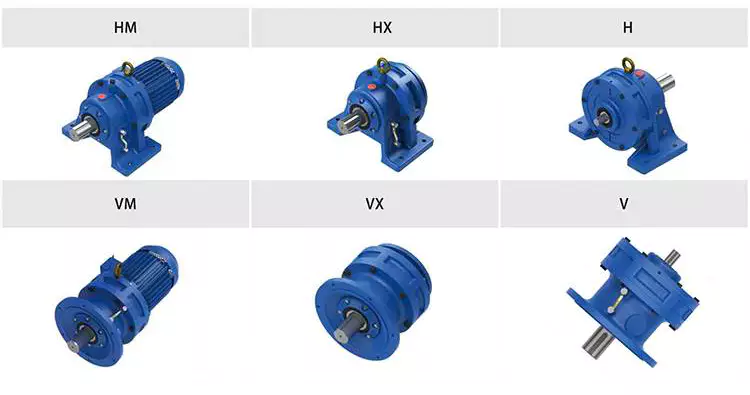
How to Use a Cyclone Gearbox
Often, a cycloidal gearbox is used in order to achieve a torque transfer from a motor or pump. This type of gearbox is often a common choice as it has a number of advantages over a regular gearbox. Its main advantage is that it is easy to make, which means that it can be incorporated into a variety of applications. However, if you want to use a cycloidal gearbox, there are a few things that you need to know. These include the operation principle, the structure and the dynamic and inertial effects that come with it.
Dynamic and inertial effects
Several studies have been carried out on the static and dynamic properties of cycloidal gears. The study of these effects is beneficial in assisting optimal design of cycloidal speed reducers.
In this paper, the dynamic and inertial effects of a two-stage cycloidal speed reducer have been investigated using the CZPT program package. Moreover, a new model for cycloidal reducers based on non-linear contact dynamics has been developed. The new model aims to predict several operational conditions.
The normal excitation contact force for the cycloid discs of the first and second stage is very similar. However, the total deformation at the contact point is different. This effect is mainly due to the system’s own oscillations. The cycloid discs of the second stage turn around the ring gear roller with a 180deg angle. This angle is a significant contributor to the torque loads. The total excitation force on the cycloid discs of first and second stage is 1848 N and 2068.7 N, respectively.
In order to analyze the contact stress, different gear profiles were investigated. The mesh density was considered as an important design criterion. It was found that a bigger hole reduces the material content of the cycloidal disc and results in more stresses.
Moreover, it is possible to reduce the contact forces in a more efficient manner by changing the geometric parameters. This can be done by mesh refinement along the disc width. The cycloidal disc has the greatest influence on the output results.
The efficiency of a cycloidal drive increases with the increase in load. The efficiency of a cycloidal reducer also depends on the eccentricity of the input shaft and the cycloidal plate. The efficiency curve for small loads is linear. However, for the larger loads, the efficiency curve becomes more non-linear. This is because the stiffness of the cycloid reducer increases as the load increases.
Structure
Despite the fact that it looks like a complicated engineering puzzle, the construction of a cycloidal gearbox is actually quite simple. The key elements are the base, the load plate and the thrust bearing. All these elements work together to create a stable, compact gearbox.
The base is a circular section with several cylindrical pins around its outer edge. The pins are fixed on a fixed ring that holds them in a circular path. The ring serves as a reference circle. The circle’s size is approximately 5mm in diameter.
The load plate is a series of threaded screw holes. These are arranged 15mm away from the center. These are used to anchor external structures. The load plate must be rotated around the X and Y axis.
The thrust bearing is placed on top of the load plate. The bearing is made of an internal diameter of 35mm and an external diameter of 52mm. It is used to allow rotation around the Z axis.
The cycloidal disc is the centerpiece of the cycloidal gearbox. The disc has holes for the pins that drive the output shaft. The holes are larger than those used in output roller pins. The disc also has a reduced eccentricity.
The pins are attached to the cycloidal disc by rolling pins. The pins are made of a material that provides mechanical support for the drive during high-torque situations. The pins have a 9mm external diameter. The disc has a number of lobes and is rotated by one lobe per shaft revolution.
The cycloidal gearbox also has a top cover that helps keep the components together. The cover has a pocket for tools. The top cover also has threads that screw into the casing.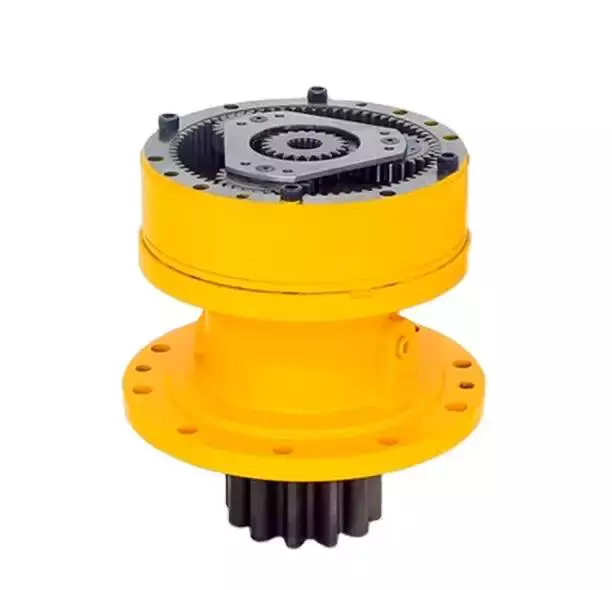
Operation principle
Among many types of gear transmissions, cycloidal gearboxes are used in heavy machinery and multi-axis robots. They are highly effective, compact and capable of high ratios. In addition, they have an overload capability.
Cycloid disks are driven by eccentric shafts that rotate around fixed ring pins. Roller pins of the pin disc engage with holes in the cycloidal disc. These roller pins drive the pin disc and the pin disc transfers the motion to the output shaft.
Unlike conventional gear drives, cycloidal drives have low backlash and high torsional stiffness. They are ideally suited to heavy loads and all drive technologies. The lower mass and compact design of the cycloidal disk also contributes to its high efficiency and positioning accuracy.
The cycloidal disc plays a central role in the gearbox kinematics. It rotates around a fixed ring in a circle. When the disc is pushed against the ring gear, the pins engage with the disc and the roller pins rotate around the pins. This rotating motion generates vibration, which travels through the driven shafts.
Cycloid discs are typically designed with a short cycloid, so that the eccentricity is minimized. This reduces unbalance forces at high speeds. Ideally, the number of lobes on the cycloid is smaller than the number of surrounding pins. This reduces the amount of Hertzian contact stress.
Unlike planetary gears, cycloidal gears have high accuracy and are capable of withstanding shock loads. They also experience low friction and less wear on tooth flanks. They also have higher efficiency and load capacity.
Cycloid gears are generally more difficult to manufacture than involute gears. Cycloid gears are not suitable for stacking gear stages. They require extreme accuracy for manufacturing. However, their smaller size and low backlash, high torsional stiffness, and low vibration make them ideal for use in heavy machines.
Involute gear tooth profile
Almost all gears are manufactured with an involute gear tooth profile. Cycloid gears are also produced with this profile. Compared with involute gears, cycloid gears are stronger and can transmit more power. However, they can also be more difficult to manufacture. This makes them costlier.
The involute gear tooth profile is a smooth curve. It is derived from the involute curve of a circle. A tangent to the base circle is the normal at any point of an involute.
This curve has properties that allow the involute gear teeth to transfer motion in perpendicular direction. It is also the path traced by the end of the string unwrapping from a cylinder.
An involute profile has the advantage of being easy to manufacture. It also allows for smooth meshing despite misalignment of the centre distance. This profile is also preferred over a cycloid tooth profile, but it is not the best in every regard.
Cycloid gear teeth are also made of two curves. Unlike involute teeth, cycloid gear teeth have a consistent radius. Cycloid gears are less likely to produce noise. But they are also more expensive to manufacture.
Involute teeth are easier to manufacture because they have only one curve. Cycloid gears can also be made with a rack type cutter. This makes them cheaper to manufacture. However, they require an expert design. They can also be manufactured with a gear shaper that includes a pinion cutter.
The tooth profiles that satisfy the law of gear-tooth action are sometimes called conjugate profiles. The involute profile is the most common of these. It allows for constant torque transmission.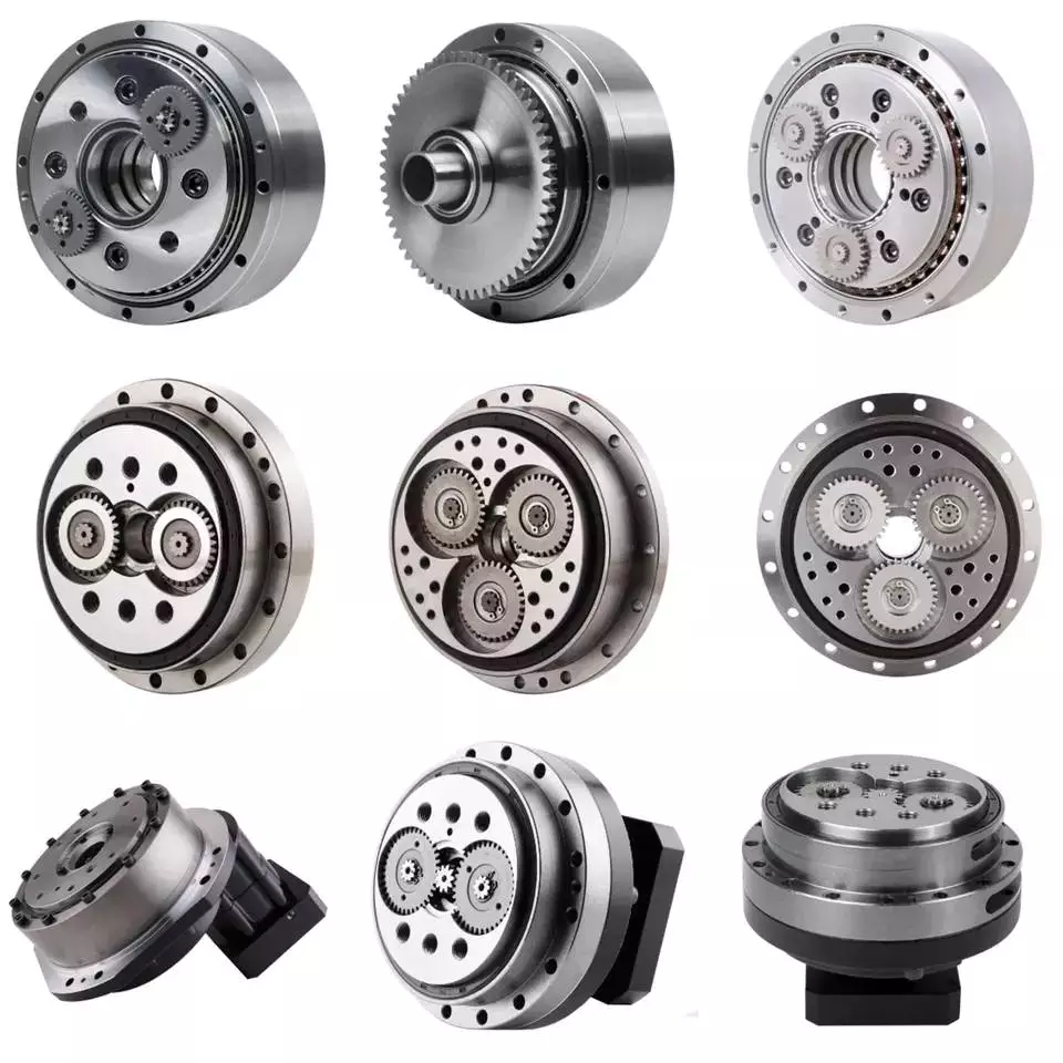
Backlash
Typically, cycloidal drives provide a high ratio of transmission with no backlash. This is because the cycloid disc is driven by an eccentric shaft. During rotation, the cycloid disc rotates around a fixed ring. This ring also rotates independently of the center of gravity.
The cycloid disc is typically shortened to reduce the eccentricity. This helps to minimize the unbalance forces that may occur at high speeds. The cycloid also offers a larger gear ratio than traditional gears. This provides a better positional accuracy.
Cycloid drives also have a high torsional stiffness. This provides greater torsional resilience and shock load capabilities. This is important for a number of reasons, such as in heavy-duty applications.
Cycloid drives also have lower mass. These benefits make them ideally suited for all drive technologies. The design also allows for higher torsional stiffness and service life. These drives also have a much smaller profile.
Cycloid drives are also used to reduce speed. Because of the high torsional stiffness of the cycloid, they also have high positioning accuracy.
Cycloid drives are well-suited to a variety of applications, including electric motors, generators, and pump motors. They are also highly resistant to shock loads, which is important in a variety of applications. This design is ideal for applications that require a large transmission ratio in a compact design.
Cycloid drives also have the advantage of minimizing the clearance between the mating components. This helps to eliminate interference and ensure a positive fit. This is particularly important in gearboxes. It also allows for the use of a load cell and potentiometer to determine the backlash of the gearbox.

editor by CX 2023-05-12
China Standard CZPT Auto Parts Power Steering Rack Gear Box for Mercedes Benz W220 OE 2204601500 with high quality
Error:获取返回内容失败,
Your session has expired. Please reauthenticate.
| Length | 184 | mm |
| Thickness | 132 | mm |
| Width | 122 | mm |
| Thread Size | M12X1.5 |
###
| Mounting Type | Hydro Bearing |
| Dimension | OEM Standard |
| Material | Steel Elastomer |
| Weight | 24Kg |
| Length | 184 | mm |
| Thickness | 132 | mm |
| Width | 122 | mm |
| Thread Size | M12X1.5 |
###
| Mounting Type | Hydro Bearing |
| Dimension | OEM Standard |
| Material | Steel Elastomer |
| Weight | 24Kg |
The Different Types of Gearboxes
There are many different types of gearboxes. Some brands have more than one type. In this article, we’ll discuss the planetary gearbox, the worm reduction gearbox, the shaft mounted gearbox, and the one speed gearbox. This article will also help you determine which type of gearbox is best for your vehicle. And don’t worry if you don’t know the terminology yet. We’ll explain each type in detail so that you know what you’re getting yourself into.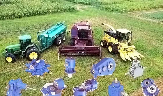
Planetary gearbox
Planetary gears have many advantages. The multiple gears in a planetary gearbox mesh simultaneously during operation. As such, they provide high efficiency and transmit high transmittable torque. These gears are widely used in various industries and are resistant to high shock loads and demanding conditions. CZPT is one of the companies that offer planetary gearboxes. Its products do not require special tools for assembly, and its scalable design minimizes safety stock.
Among the numerous benefits of planetary gearing is its compactness and lightweight. As such, it is suitable for wide applications with space and weight constraints. However, to truly appreciate its benefits, it is necessary to understand its mechanisms. Here are some of the most common details about planetary gearing:
The planetary gearbox has two mounted gears: an input shaft and an output shaft. Each gear has multiple teeth that are attached to a carrier and rotate with the input shaft. The carrier is connected to the output shaft. A planetary gear is mounted on both gears via a carrier. The carrier rotates in order to drive the planetary gear. The sun gear is often the input gear. The other gear is called the outer gear.
Planetary gearboxes are highly customizable. The size, mounting, and housing options vary, as do the reduction ratios and input speeds. Different types can be manufactured for different applications and include options such as electrical or mechanical preload. The final design of a planetary gearbox can be highly customized, based on the specifications of the application. By combining engineering excellence and ongoing innovation, planetary gearboxes provide years of trouble-free operation.
A planetary gearbox can be either an electric motor or a manual one. The latter has more features than the former, and can be used in applications where space is an issue. The primary features of a planetary gearbox include its backlash, torque, and ratio. Secondary features include noise, corrosion resistance, and construction. A planetary gearbox is a highly versatile gearbox that can drive anything from simple machinery to advanced electrical systems.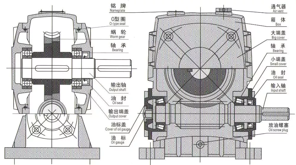
Worm reduction gearbox
The global worm reduction gearbox market report compiles key insights from the industry to help you improve your business strategy. This report will help you create a comprehensive business document that will enhance your company’s competitive edge. To obtain this report, visit our website now! Read our latest report to find out what you can expect from the global worm reduction gearbox market. Alternatively, request a sample copy for more details. Here is a sneak peek of the report:
Worm gears are made with different thread counts and are usually not matched with the CZPT standard. In general, a single thread worm should be used with a single thread worm. Worm gears have either right or left threads, and their thread count will be different as well. This type of gear is used to reduce the speed of a rotating shaft. The speed reduction ratio will be about 50 percent if the worms have the same thread count as the CZPT gears.
The standard gear set transfers power at the peak load point of a tooth, called the pitchline. The worm gear moves slowly against the wheel’s metal surface. The worm gear is also more complex than the standard gear because the worm is sliding rather than rolling. Worm gears are hard to lubricate. Moreover, the sliding contact between the gear and worm increases the complexity of the gear set. They can be a great solution for applications where noise is a significant factor.
The axial pitch and circular pitch of the worm are equal. The ratio of these two indices determines the speed of transmission. For a worm reduction gearbox to work, the axial pitch and the circular pitch must match. The pitch angle of a worm can either be left-handed or right-handed. The lead of a worm is the distance one thread travels in one revolution. The lead angle is the angle tangent to the thread helix of the cylinder’s pitch. When a worm mesh is reversed, the majority of the mesh will be on the receding arc.
Worm gears generate more heat than their counterparts, so it is important to choose a worm reduction gearbox carefully. You will want to choose the material and amount of lubricating oil carefully. Worm gears are generally made of tin bronze. The paired worms are hardened to HRC45-55. In general, they are durable, lasting up to ten years. But they will wear out – and they wear out – so you may want to consider some other factors.
Shaft-mounted gearbox
Shaft-mounted gearboxes are designed for a variety of mining and quarry applications. Their high reliability and low maintenance make them an excellent choice in these types of applications. Shaft-mounted gearboxes also feature an optional backstop device that prevents the unit from rotating in one direction. This makes them an excellent choice for applications where alignment accuracy is an issue. Here are some of the benefits of using a shaft-mounted gearbox:
Shaft-mounted gearboxes are typically constructed of aluminium, and come in sizes ranging from 050 to 125. They feature a variety of reduction ratios and ensure optimum efficiency in all operating conditions. New S series sizes, 140 and 150, extend the application range of shaft-mounted gearmotors. They are both backed by a two-year warranty. For even greater peace of mind, Shaft-mounted gearboxes are available with a range of warranty options.
The most common applications for a Shaft-mounted gearbox include traction-driven applications where a low-speed shaft is required for operation. They also are suitable for applications without a foundation, where the motor is mounted next to the reducer. To prevent the gear drive from rotating, a torque arm is attached between the motor and the shaft. Small-sized shaft-mounted gear drives are usually made without motor mount kits, which can make them an excellent choice for conveying light loads.
Another important feature of a Shaft-mounted gearbox is its mounting position. The reduced motion through the drive is redirected through the shaft, creating additional forces. These additional forces can affect the performance of the gearbox, causing vibrations and noise. Consequently, it is important to replace worn or damaged belts on a regular basis. Further, shaft-mounted gearboxes can be affected by problems with other components and amplify vibrations.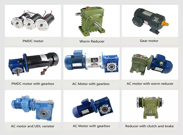
1 speed gearbox
CZPT Group Components produces one speed gearboxes. These transmissions are produced in the CZPT Group’s Kassel plant. They are compact and robust, and are designed for easy integration. The Bosch Rexroth GD1 one-speed gearbox is easy to install horizontally or vertically. The Plug and Drive system integrates the gearbox with the existing cooling system. There are many other benefits to this gearbox.
With an ID.3 electric drive motor, the maximum torque is delivered at 16,000 rpm. This single-speed transmission offers high power density and excellent noise-reduction, making it ideal for electric vehicles. The e-drive motor is extremely quiet and requires precision manufacturing. The e-drive motor also enables a wide range of driving conditions. It can reverse when needed, and reaches its maximum speed at 16,000.
The single-speed gearbox is a standard feature on most electric vehicles. Some electric vehicles, such as the Porsche Taycan, will be equipped with a two-speed gearbox. This gearbox offers more top speed and range, but it is more complex than a standard single-speed gearbox. CZPT doesn’t need to add complexity to its electric vehicles. After all, a 355 horsepower family wagon is not likely to need a dual-speed gearbox.
In addition to simplifying the transmission, the patent claims also address improvements in structural design. Fig. 5 shows a schematic representation of a transmission 50′, wherein gear sets Z1 and Z4 are exchanged between partial transmissions. This switch matrix also reflects the synchronized gears and lastshelf gears. Hydraulically betatigte Lamellenkupplungen (HBA) also form a last-shelf gear.
Another advantage of the patent claim is that it offers numerous functional freedoms, which is especially valuable in the design of an automobile. One of the patent claims identifies a tosatzlicher middle gear that allows a driver to switch between second and third gears, with a single gearbox. In a conventional one-speed transmission, the tosatzlicher middle gear is attached to the second and first part gearbox. The latter has a second and third gear.

