Product Description
Technology date:
1. Ratio range: 7.18-14062
2. Input power: 0.18-22 KW
3. Permit torque rang: ≤ 1500 N. M
4. Output speed: 0.3~205 r/min
5. Structure: Foot-mounted, flange-mounted, shaft-mounted
Characteristic:
1. Adopt optimized design, module combination, right angle output, space reduction
2. High strength and longevity gears
3. Reverse operation function, combinable with various motors, wider ratio range
4. Big output torque, smoothly startup, high efficiency.
Company Certificate:
Packaging & Shipping
Package :
SGR gearbox use standard wood case per gear motor | gear unit.
Shipping :
According to Customer requirement, we delivery products by different transport, Sea shipping, Air Transportation / Express or Truck transportation etc.
You Appoint, We Service!
Our Services
With all our activities DNV-ISO 9001, SGS -certified, we stand for top-quality service. Entrusting your gearboxes to the care of our Services.
Help protect your gearbox from wear and grinding, SGR gearbox converts torque reliably and efficiently.
We customize our CZPT planetary gear units, double enveloping worm gearbox, helical gear motor, modular design helical gear unit, worm gearbox, cycloidal gearbox etc to fit your application and meet your needs.
These features enable a reliable and safe service life of over 200 000 operational hours.
Our customers have been placing their trust in CZPT gear units since 1997. More than 500 000 gear units of our gearbox are in use reliably around the world, in many cases under very harsh conditions.
Our Honour and Patent :
ABOUT US:
ZheJiang CZPT Heavy Industry Machinery Co., Ltd.(formerly known as ZheJiang CZPT Reducer Co., Ltd. ) (sgrgear ) has accumulated rich original designing & manufacturing experience after being founded in 1996. CZPT brand planetary gear reducer has won honor of “Science and Technology Advancement Prize” awarded by the National Speed Reducer & Variator Industry Association.
We produce planetary gear units, planar double-enveloping worm gear speed reducers (cone worm gear reducer), helical-bevel gear motors, worm gear reducers, helical worm gear motors, helical gear motors and many other types of gear units. CZPT gear motors and gear units have given satisfactory performance in different industrial applications, including metallurgy, mineral, architecture, shipbuilding, petroleum combination, aviation space-flight, lift routeing, textile mechanic, cement, pharmaceuticals, pumps, general mechanic and other domain.
With the advantage of high quality & competitive price, CZPT gear motor and gear units are widely welcomed in the domestic market and exported to Southeast Asia, Middle Asia, North America and European countries etc.
With the excellent testing program, CZPT company is always keeping up with the most advanced technology in the world. We have already acquired DNV-ISO9001: 2008 certificate,SGS, CE etc and a patent on CZPT branded gearbox.
We have adopted advanced CAD and CIMS in design & manufacture, which help our engineers develop 3 – 5 series of new efficient products each year. All staff in sales & service department are well trained termly, thus you will be always warmly welcomed and understood by our company.
FAQ
- Q: What is your business type?
- A: CZPT is gearbox manufacturer and Solutions Provider, we are experts of the planetary gear reducer, cone worm gearbox, modular design helical gear motor, worm gearbox etc. A suitable model will offer to you according to your requirement, besides, CZPT also has professional technical team special in the custom gearbox and gearbox repair.
- Q: How long can you provide products guarantee Period?
- A: Based on different gearbox types, 12-18 months.
- Q: What’s Certification your product acquiry ?
- A: DNV-ISO9001:2008 ,SGS ,CE etc. and new products patent.
- Q: How many technical employees in your company?
- A: We have 10 engineers in our R&D Dep., included 2 engineers who enjoy government ‘s allowance.
- Q: Where is your company & how to contact you?
- A: Our factory located in No.879 , JinLiu Rd, JinShan District , ZheJiang City , China .
| Application: | Motor, Machinery, Marine, Agricultural Machinery, Industry |
|---|---|
| Function: | Distribution Power, Clutch, Change Drive Torque, Change Drive Direction, Speed Changing, Speed Reduction |
| Layout: | Angle |
| Hardness: | Hardened |
| Installation: | Horizontal Type |
| Step: | Single-Step |
| Samples: |
US$ 200/Piece
1 Piece(Min.Order) | |
|---|
| Customization: |
Available
| Customized Request |
|---|
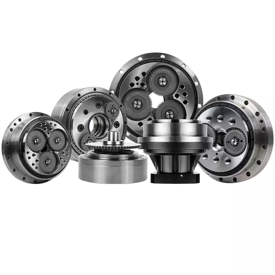
How to Calculate Transmission Ratio for a Cycloidal Gearbox
Using a cycloidal gearbox can be very useful in a wide variety of situations. However, it’s important to understand how to use it properly before implementing it. This article discusses the benefits of using a cycloidal gearbox, how to calculate the transmission ratio, and how to determine the effects of dynamic and inertial forces on the gearbox.
Dynamic and inertial effects
Various studies have been done to study the dynamic and inertial effects of cycloidal gearboxes. These studies have been performed using numerical, analytical and experimental methods. Depending on the nature of the load and its distribution along the gear, a variety of models have been developed. These models use finite element method to determine accurate contact stresses. Some of these models have been developed to address the nonlinear elasticity of contacts.
Inertial imbalance in a cycloidal gearbox causes vibration and can affect the efficiency of the device. This can increase mechanical losses and increase wear and tear. The efficiency of the device also depends on the torque applied to the cycloidal disk. The effectiveness of the device increases as the load increases. Similarly, the nonlinear contact dynamics are also associated with an increase in efficiency.
A new model of a cycloidal reducer has been developed to predict the effects of several operational conditions. The model is based on rigid body dynamics and uses a non-linear stiffness coefficient. The model has been validated through numerical and analytical methods. The model offers drastic reduction in computational costs. The model allows for a quick analysis of several operational conditions.
The main contribution of the paper is the investigation of the load distribution on the cycloidal disc. The study of this aspect is important because it allows for an analysis of the rotating parts and stresses. It also provides an indication of which gear profiles are best suited for optimizing torque transmission. The study has been conducted with a variety of cycloidal gearboxes and is useful in determining the performance of different types of cycloidal gearboxes.
To study the load distribution on the cycloidal disc, the authors investigated the relationship between contact force, cycloidal gearboxes and different gear profiles. They found that the non-linear contact dynamics have a large impact on the efficiency of a cycloidal gearbox. The cycloidal gearbox is an ideal solution for applications that involve highly dynamic servos. It can also be used in machine tool applications and food processing industries.
The study found that there are three common design principles of cycloidal reducers. These are the contact force distribution, the speed reduction and the trochoidal profile of the cycloidal disc. The trochoidal profile has to be defined carefully to ensure correct mating of the rotating parts. The trochoidal profile provides an indication of which gear profiles are best for optimizing torque transmission. The contact force distribution can be improved by refining the mesh along the disc’s width.
As the input speed increases, the efficiency of the reducer increases. This is because contact forces are constantly changing in magnitude and orientation. A cycloidal reducer with a one tooth difference can reduce input speed by up to 87:1 in a single stage. It also has the ability to handle high-cycle moves without backlash.
Transmission ratio calculation
Getting the correct transmission ratio calculation for a cycloidal gearbox requires a good understanding of what a gearbox is, as well as the product that it is being used for. The correct ratio is calculated by dividing the output speed of the output gear by the input speed of the input gear. This is usually accomplished by using a stopwatch. In some cases, a catalog or product specification may be required. The correct ratio is determined by a combination of factors, such as the amount of torque applied to the mechanism, as well as the size of the gears involved.
A cycloidal gear is a type of gear tooth profile that can be represented using a spline. It is also possible to model a gear with a cycloidal profile by using a spline to connect points against the beginning of a coordinate system. This is important in the design and functionality of a gear.
There are many different gears used in machines and devices. These include the herringbone gear, the helical gear and the spiral bevel gear. The best transmission ratios are typically obtained with a cycloidal gearbox. In addition to ensuring the accuracy of positioning, a cycloidal gearbox provides excellent backlash. Cycloid gears have a high degree of mechanical efficiency, low friction, and minimal moment of inertia.
A cycloidal gearbox is often referred to as a planetary gearbox, though it is technically a single-stage gearbox. In addition to having a ring gear, the gearbox has an eccentric bearing that drives the cycloidal disc in an eccentric rotation. This makes the cycloidal gearbox a good choice for high gear ratios in compact designs.
The cycloid disc is the key element of a cycloidal gearbox. The cycloid disc has n=9 lobes, and each lobe of the disc moves by a lobe for every revolution of the drive shaft. The cycloid disc is then geared to a stationary ring gear. The cycloidal disc’s lobes act like teeth on the stationary ring gear.
There are many different gears that are classified by the profile of the gear teeth. The most common gears are the involute and helical gears. Most motion control gears include spur designs. However, there are many other types of gears that are used in various applications. The cycloidal gear is one of the more complicated gears to design. The cycloid disc’s outline can be represented using markers or smooth lines, though a scatter chart will also do.
The cycloid disc’s lobes rotate on a reference pitch circle of pins. These pins rotate 40 deg during the eccentric rotation of the drive shaft. The pins rotate around the disc to achieve a steady rotation of the output shaft.
The cycloid disc’s other obvious, and possibly more important, feature is the’magic’ number of pins. This is the number of pins that protrude through the face of the disc. The disc has holes that are larger than the pins. This allows the pins to protrude through the disc and attach to the output shaft.
Application
Whether you’re building a robot drive or you’re simply looking for a gearbox to reduce the speed of your vehicle, a cycloidal gearbox is a great way to achieve a high reduction ratio. Cycloidal gearboxes are a low-friction, lightweight design that has an extremely stable transmission. They are suitable for industrial robots and can be used in many applications, including positioning robots.
Cycloidal gearboxes reduce speed by using eccentric motion. The eccentric motion enables the entire internal gear to rotate in wobbly cycloidal motion, which is then translated back into circular rotation. This eliminates the need for stacking gear stages. Cycloidal gearboxes also have less friction, higher strength, and greater durability than conventional gearboxes.
The cycloidal gearbox is also used in a number of applications, including marine propulsion systems, and robot drives. Cycloidal gearboxes reduce vibration by using offset gearing to cancel out vibrations.
Cycloidal gears have lower friction, higher strength, and better torsional stiffness than involute gears. They also have a reduced Hertzian contact stress, making them better than involute gears for use with shock loads. They also have a smaller size and weight than conventional gearboxes, and they have a higher reduction ratio than involute gears.
Cycloidal gears are typically used to reduce the speed of motors, but they also offer a number of other advantages. Cycloidal gearboxes have a smaller footprint than other gearboxes, allowing them to fit into confined spaces. They also have low backlash, allowing for precise movement. Cycloidal gears have a higher efficiency, resulting in lower power requirements and lower wear.
The cycloidal disc is one of the most important components of the gearbox. Cycloidal discs are normally designed with a short cycloid, which minimizes the eccentricity of the disc. They are also designed with a shortened flank, resulting in better strength and less stress concentration. Cycloidal discs are typically geared to a stationary ring gear. The cycloid is designed to roll around the stationary ring pins, which push against the circular holes in the disc. Cycloidal gearboxes typically employ two degrees of shift.
Cycloidal drives are ideal for heavy load applications. They also have high torsional stiffness, which makes them highly resistant to shock loads. Cycloidal drives also offer a high reduction ratio, which can be achieved without the need for a large input shaft. They are also compact and have a high service life.
The output shaft of a cycloidal gearbox always has two degrees of shifting, which ensures that the input and output shafts always rotate at a different speed. The output shaft would be a pin casing around the drive disks, which would also allow for easy maintenance.
Cycloidal gearboxes are also very compact and lightweight, so they are ideal for use in industrial robots. The cycloidal gearbox reducer is the most stable, low-vibration reducer in industrial robots, and it has a wide transmission ratio range.

editor by CX 2023-10-26
China Aluminum Gearbox Cast Iron Housing Transmission Drive Motor Shaft Nmrv Smr Series Reduction Helical Cycloidal Cyclo Planetary Worm Gearboxes Speed Gear Reducer cycloidal gearbox backlash
Merchandise Description
Features
1.Wide transmission rate, strong output torque
2.Compact mechanical structure, light weight, small volume&Good heat-dissipating
3.Smooth operation with lower noise or vibration
4.Easy mounting, free linking, high efficiency
5. Perfect SUBSTITUDE FOR MOTOVARIO AND CZPT PRODUCTS
Programs
Wide range of application,including light industry of food &beverage, Cement,
bundle,construction material,chemicals and etc.
Technical data:
| Product | RV one hundred thirty one hundred fifty |
| Solitary unit versions | NMRV – fitted for motor flanged coupling, NRV – with enter shaft, NMRV-E motor flanged coupling with worm extension shaft, NRV-E with double extension worm shaft, |
| Power | .06—-15KW |
| Single unit reduction ratio | 1:5 7.5 80 100 |
| Output torque | 2.6—1195N.M |
| Worm shaft substance | 20CrMnTi with carburizing and quenching.The hardness of surface area is 56-62HRC with carbonized layer .5-.8mm |
| Worm wheel material | worm mandrel is HT250,and worm ring gear,ZQSn10-1,hardness is 60HRC |
Right after-sale services:
1 year guarantee,matter to appropriate operation and installationfree specialized support all the time.
|
US $25 / Piece | |
1 Piece (Min. Order) |
###
|
Shipping Cost:
Estimated freight per unit. |
To be negotiated| Freight Cost Calculator |
|---|
###
| Application: | Motor |
|---|---|
| Hardness: | Hardened |
| Type: | Worm and Wormwheel |
###
| Samples: |
US$ 30/Piece
1 Piece(Min.Order) |
|---|
###
| Customization: |
Available
|
|---|
###
| Model | RV025 030 040 050 063 075 090 110 130 150 |
| Single unit versions | NMRV – fitted for motor flanged coupling, NRV – with input shaft, NMRV-E motor flanged coupling with worm extension shaft, NRV-E with double extension worm shaft, |
| Power | 0.06—-15KW |
| Single unit reduction ratio | 1:5 7.5 10 15 20 25 30 40 50 60 80 100 |
| Output torque | 2.6—1195N.M |
| Worm shaft material | 20CrMnTi with carburizing and quenching.The hardness of surface is 56-62HRC with carbonized layer 0.5-0.8mm |
| Worm wheel material | worm mandrel is HT250,and worm ring gear,ZQSn10-1,hardness is 60HRC |
|
US $25 / Piece | |
1 Piece (Min. Order) |
###
|
Shipping Cost:
Estimated freight per unit. |
To be negotiated| Freight Cost Calculator |
|---|
###
| Application: | Motor |
|---|---|
| Hardness: | Hardened |
| Type: | Worm and Wormwheel |
###
| Samples: |
US$ 30/Piece
1 Piece(Min.Order) |
|---|
###
| Customization: |
Available
|
|---|
###
| Model | RV025 030 040 050 063 075 090 110 130 150 |
| Single unit versions | NMRV – fitted for motor flanged coupling, NRV – with input shaft, NMRV-E motor flanged coupling with worm extension shaft, NRV-E with double extension worm shaft, |
| Power | 0.06—-15KW |
| Single unit reduction ratio | 1:5 7.5 10 15 20 25 30 40 50 60 80 100 |
| Output torque | 2.6—1195N.M |
| Worm shaft material | 20CrMnTi with carburizing and quenching.The hardness of surface is 56-62HRC with carbonized layer 0.5-0.8mm |
| Worm wheel material | worm mandrel is HT250,and worm ring gear,ZQSn10-1,hardness is 60HRC |
Condition Monitoring of Cyclone Gearboxes
Whether you’re considering using a cycloidal gearbox in your home, office, or garage, you’ll want to make sure it’s made of quality material. You also want to make sure it’s designed properly, so it won’t be damaged by vibrations.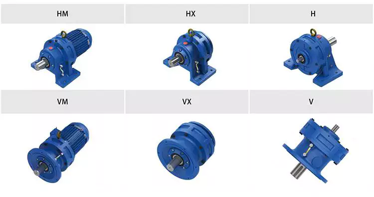
Planetary gearboxes
Compared to cycloidal gearboxes, planetary gearboxes are lighter and more compact, but they lack the precision and durability of the former. They are better suited for applications with high torque or speed requirements. For this reason, they are usually used in robotics applications. But, cycloidal gearboxes are still better for some applications, including those involving shock loads.
There are many factors that affect the performance of gearboxes during production. One of these is the number of teeth. In the case of planetary gearboxes, the number of teeth increases with the number of planets. The number of teeth is reduced in cycloidal gearboxes, which results in higher transmission ratios. These gearboxes also have lower breakaway torques, which means that they can be controlled more easily by the user.
A cycloid gearbox is comprised of three main parts: the ring gear, the sun gear, and the input shaft. The ring gear is fixed in the gearbox, while the sun gear transmits the rotation to the planet gears. The input shaft transfers motion to the sun gear, which in turn transmits it to the output shaft. The output shaft has a larger torque than the input shaft.
Cycloid gears have better torsional stiffness, lower wear, and lower Hertzian contact stress. However, they are also larger in size and require highly accurate manufacturing. Cycloid gears can be more difficult to manufacture than involute gears, which require large amounts of precision.
Cycloid gears can offer transmission ratios up to 300:1, and they can do this in a small package. They also have lower wear and friction, which makes them ideal for applications that require a high transmission ratio.
Cycloid gearboxes are usually equipped with a backlash of about one angular minute. This backlash provides the precision and control necessary for accurate movement. They also provide low wear and shock load capacity.
Planetary gearboxes are available in single and two-stage designs, which increase in length as stages are added. In addition to the two stages, they can be equipped with an optional output bearing, which takes up mounting space. In some applications, a third stage is also available.
Involute gears
Generally, involute gears are more complex to manufacture than cycloidal gears. For example, an involute gear tooth profile has a single curve while a cycloidal gear tooth profile has two curves. In addition, the involute curve is not within the base circle.
The involute curve is a very important component of a gear tooth and it can significantly influence the quality of contact meshing between teeth. Various works have been done on the subject, mainly focusing on the operating principles. In addition, the most important characteristic of the double-enveloping cycloid drive is its double contact lines between the meshing tooth pairs.
Cycloid gears are more powerful, less noisy, and last longer than involute gears. They also require less manufacturing operations during production. However, cycloid gears are more expensive than involute gears. Involute gears are more commonly used in linear motions while cycloid gears are used for rotary motions.
Although cycloid gears are more technically advanced, involute gears have the superior quality and are more aesthetically pleasing. Cycloid gears are used in various industrial applications such as pumps and compressors. They are also widely used in the watch industry. Nevertheless, involute gears have not yet replaced cycloid gears in the watch industry.
The cycloid disc has a number of pins around its outer edge, while an involute gear has only a single curve for the teeth. In addition, cycloid gears have a more robust and reliable design. Involute gears, on the other hand, have a cheaper rack cutter and less expensive involute teeth.
The cycloid disc’s transmission accuracy is about 98.5%, while the ring gear’s transmission accuracy is about 96%. The cycloid disc’s rotational velocity has a magnitude of 3 rad/s. A small change in the center distance does not affect the transmission accuracy. However, rotational velocity fluctuation can affect the transmission accuracy.
Cycloid gears also have the cycloid gear disc’s rotational velocity. The disc has N lobes. However, the cycloid gear disc’s transmission accuracy is still not perfect. This is because of the large rotational angles between the lobes. This also makes it difficult to manufacture.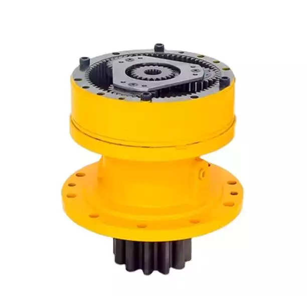
Vibrations
Using modern techniques for vibration diagnostics and data-driven methods, this article presents a new approach to condition monitoring of cycloidal gearboxes. This approach focuses on detecting the root cause of gearbox failure. The article aims to provide a unified approach to gear designers.
A cycloidal gearbox is a high-precision gearbox that is used in heavy-duty machines. It has a large reduction ratio, which makes it necessary to have a very large input speed. Cycloid gears have high accuracy, but they are susceptible to vibration issues. In this article, the authors describe how a cycloidal gearbox works and how vibrations are measured. They also show how this gearbox can be used to detect faults.
The gearbox is used in positioners, multi-axis robots, and heavy-duty machines. The main characteristics of this gearbox are the high accuracy, the overload capacity, and the large reduction ratio.
There is little documentation on vibrations and condition monitoring of cycloidal gearboxes. The authors describe their approach to the problem, using a cycloidal gearbox and a testing bench. Their approach involves measuring the frequency of the gearbox with different input speeds.
The results show a good separation between the healthy and damaged states. Fault frequencies show up in the lower orders of frequencies. Faults can be detected using binning, which eliminates the need for a tachometer. In addition, binning is combined with Principal Component Analysis to determine the state of the gearbox.
This method is compared to traditional techniques. In addition, the results show how binning can be used to calculate the defect frequencies of the bearings. It is also used to determine the frequencies of the components.
The signals from the test bench are acquired using four sensors. These sensors are medium sensitivity 100 mV/g accelerometers. The signals are then processed using different signal processing techniques. The results show that the vibration signals are correlated with the internal motion of the gearbox. This information is used to identify the internal frequency of the transmission.
The frequency analysis of vibration signals is performed in cyclostationary and noncyclostationary conditions. The signals are then analyzed to determine the magnitude of the gear meshing frequency.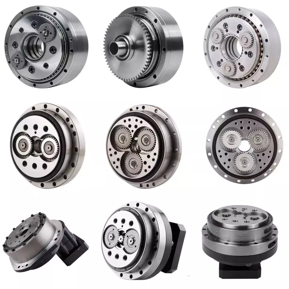
Design
Using precision gearboxes, servomotors can now control heavy loads at high speed. Unlike cam indexing devices, cycloidal gears provide extremely accurate positioning and high torque. They also provide excellent torsional stiffness and shock load capacity.
Cycloid gears are specially designed to minimize vibration at high RPM. Unlike involute gears, they are not stacked, which reduces friction and forces experienced by each tooth. In addition, cycloidal gears have lower Hertzian contact stress.
Cycloid gears are often used in multi-axis robots for positioners. They can provide transmission ratios as high as 300:1 in a compact package. They are also used in first joints in heavy machines. However, they require extremely accurate manufacturing. They are also more difficult to produce than involute gears.
A cycloidal gearbox is a type of planetary gearbox. Cycloid gears are specially designed for high gear ratios. They also have the ability to provide a large reduction ratio in a single stage. They are increasingly used in first joints in heavy machines. They are also becoming more common in robotics.
In order to achieve a large reduction ratio, the input speed of the gear must be very high. Generally, the input speed is between 500 rpm and 4500 rpm. However, in some cases, the input speed may be lower.
A cycloid is formed by rolling a rolling circle on a base circle. The ratio between the rolling circle diameter and the base circle diameter determines the shape of the cycloid. A hypocycloid is formed by rolling primarily on the inside of the base circle, while an epicycloid is formed by rolling primarily on the outside of the base circle.
Cycloid gears have a very small backlash, which minimizes the forces experienced by each tooth. These gears also have a good torsional stiffness, low friction, and shock load capacity. They also provide the best positioning accuracy.
The cycloidal gearbox was designed and built at Radom University. The design was based on three different cycloidal gears. The first pair had the external profile at the nominal dimension, while the second pair had the profile minus tolerance. The load plate had threaded screw holes arranged 15 mm away from the center.

editor by czh 2023-01-13
China Transmission Motor Gearbox Unit Wp Nmrv Swl Screw Drive Lifts Stepper Cyclo Cycloidal Extruder Helical Planetary Bevel Worm Speed Variator Gear Reducer Gearbox with Best Sales
Product Description
Transmission Motor Gearbox Unit Wp Nmrv Swl Screw Drive Lifts Stepper Cyclo Cycloidal Extruder Helical Planetary Bevel Worm Speed Variator Gear Reducer Gearbox
Features
1. Compact structure and simple assembly;
2. Wide speed ranges and high torque;
3. Low noise, good sealing performance, high efficiency;
4. Stable and safe, long lifetime, universal;
5. Multi-structure, various assembling methods
Product Photos
Product Description
| ANG Helical Gear Reducer | |
| Model | R17 ~ 187, F37-177, K37-187, S37-97, HB01-26 |
| Input power | 0.06kw ~ 5000kw |
| Input speed | 750rpm ~ 3000rpm |
| Reduction ratio | 1/1.3 ~ 1/27000 |
| Input motor | AC (1 phase or 3 phase) / DC / BLDC motor |
| Install type | Foot / Solid shaft / Hollow shaft / Output flange… |
| Efficiency | 94% ~ 98 % for R F K series |
| Material of housing | die-cast aluminum / Cast iron / Stainless steel |
| Precision of gear | Accurate grinding, class 6 |
| Heat treatment | Carburizing and quenching |
| Accessories | Brake / Flange / Motor adapter / Torque arm … |
Advantages
FAQ
Q: Can you make the gearbox with customization?
A: Yes, we can customize per your request, like power, voltage, speed, shaft size, flange, terminal box, IP grade, etc.
Q: Do you provide samples?
A: Yes. The sample is available for testing.
Q: What is your MOQ?
A: It is 1pcs for the beginning of our business.
Q: What’s your lead time?
A: Standard product need 5-30days, a bit longer for customized products.
Q: Do you provide technical support?
A: Yes. Our company have design and development team, we can provide technical support if you
need.
Q: How to ship to us?
A: It is available by air, or by sea, or by train.
Q: How to pay the money?
A: T/T and L/C are preferred, with a different currency, including USD, EUR, RMB, etc.
Q: How can I know the product is suitable for me?
A: >1ST confirm drawing and specification >2nd test sample >3rd start mass production.
Q: Can I come to your company to visit?
A: Yes, you are welcome to visit us at any time.
Q: How shall we contact you?
A: You can send inquiry directly, and we will respond within 24 hours.
|
US $100-300 / Piece | |
1 Piece (Min. Order) |
###
| Application: | Motor, Machinery |
|---|---|
| Function: | Change Drive Torque |
| Layout: | Coaxial |
| Hardness: | Hardened Tooth Surface |
| Installation: | Horizontal Type |
| Step: | Three-Step |
###
| Samples: |
US$ 300/Piece
1 Piece(Min.Order) |
|---|
###
| Customization: |
Available
|
|---|
###
| ANG Helical Gear Reducer | |
| Model | R17 ~ 187, F37-177, K37-187, S37-97, HB01-26 |
| Input power | 0.06kw ~ 5000kw |
| Input speed | 750rpm ~ 3000rpm |
| Reduction ratio | 1/1.3 ~ 1/27000 |
| Input motor | AC (1 phase or 3 phase) / DC / BLDC motor |
| Install type | Foot / Solid shaft / Hollow shaft / Output flange… |
| Efficiency | 94% ~ 98 % for R F K series |
| Material of housing | die-cast aluminum / Cast iron / Stainless steel |
| Precision of gear | Accurate grinding, class 6 |
| Heat treatment | Carburizing and quenching |
| Accessories | Brake / Flange / Motor adapter / Torque arm … |
|
US $100-300 / Piece | |
1 Piece (Min. Order) |
###
| Application: | Motor, Machinery |
|---|---|
| Function: | Change Drive Torque |
| Layout: | Coaxial |
| Hardness: | Hardened Tooth Surface |
| Installation: | Horizontal Type |
| Step: | Three-Step |
###
| Samples: |
US$ 300/Piece
1 Piece(Min.Order) |
|---|
###
| Customization: |
Available
|
|---|
###
| ANG Helical Gear Reducer | |
| Model | R17 ~ 187, F37-177, K37-187, S37-97, HB01-26 |
| Input power | 0.06kw ~ 5000kw |
| Input speed | 750rpm ~ 3000rpm |
| Reduction ratio | 1/1.3 ~ 1/27000 |
| Input motor | AC (1 phase or 3 phase) / DC / BLDC motor |
| Install type | Foot / Solid shaft / Hollow shaft / Output flange… |
| Efficiency | 94% ~ 98 % for R F K series |
| Material of housing | die-cast aluminum / Cast iron / Stainless steel |
| Precision of gear | Accurate grinding, class 6 |
| Heat treatment | Carburizing and quenching |
| Accessories | Brake / Flange / Motor adapter / Torque arm … |
Types of Vehicle Gearboxes
In a vehicle, there are many types of gearboxes available. There are planetary gearboxes, Coaxial helical gearboxes, and skew bevel helical gearboxes, among others. In this article, we’ll cover all of them and help you determine which type of gearbox would be right for your vehicle. Also, we’ll discuss how each differs from the others.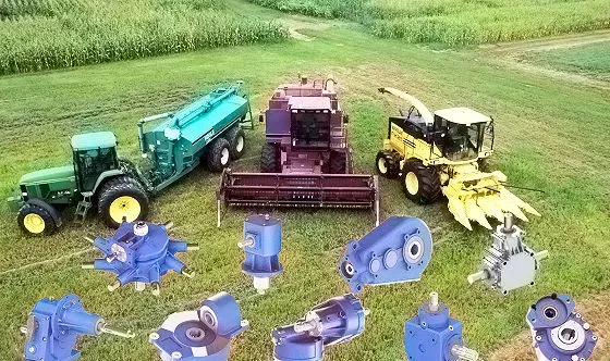
planetary gearbox
A planetary gearbox is composed of three main components: a sun gear, an input bevel gear, and an output shaft. A planetary gearbox can have different output torques and ratios. The basic model of a planetary gearbox is highly efficient and transmits 97% of the power input. There are several kinds of planetary gearboxes, depending on the type of operation. In general, there are three types: the simple, the intermediate, and the complex.
The price of a planetary gearbox can vary a lot, and it’s important to know what you’ll need. Different manufacturers produce different planetary gearboxes, so check with a manufacturer to see what they have available. Make sure to check the quality of the planetary gearbox before making a final purchase. In addition, be sure to compare the prices and the availability of a particular product. A quality planetary gearbox will provide years of trouble-free operation and will not break your bank.
Planetary gears feature an integer number of teeth. Each planet has teeth that must mesh with its ring or sun. The number of planets, ring, and tooth count of each gear determine whether the teeth mesh. Some planets have fewer teeth than others, so they mesh better than others. However, compound planets can be more flexible and achieve higher reduction ratios. If you’re looking for a planetary gearbox for your next project, consider getting in touch with a manufacturer who specializes in this technology.
When it comes to construction, a planetary gearbox is no exception. It’s extremely important to choose the right planetary gear for your application, because an imbalance in the planet gear can cause increased wear and failure. Moreover, the compact size of a planetary gear ensures maximum heat dissipation. However, a planetary gear box may require cooling in some applications. A planetary gearbox will make your life easier, and it will give you years of trouble-free operation.
Straight bevel helical gearbox
The Straight bevel helical gearbox has a number of advantages, but it has a relatively short manufacturing process. Its most popular application is in the automotive industry, where it is used in many types of vehicles. Other applications include heavy and light equipment and the aviation and marine industries. Below is a brief introduction to this gearbox type. Read on to learn about its benefits. This type of gearbox is one of the easiest to manufacture.
The spiral bevel gear has larger teeth than straight bevel gears, resulting in a smoother, quieter rotation. It can handle high-speed heavy loads with less vibration. Spiral bevel gears are classified by their tooth form and cutting method. Straight bevel gears are easier to design and manufacture, but spiral bevel gears are more expensive. Both designs are suitable for high-speed, heavy-load operations, and general manufacturing applications.
In addition to being easy to install, the modular bevel gears have many advantages. They have an exceptionally high degree of interchangeability and feature the highest standards of component integrity. They can also be tailored to meet your specific requirements. The advantages of this gearbox type include high precision, optimum performance, and low noise. And because they are modular, they can be produced in a variety of finishes. These include stainless steel, titanium, and bronze.
Straight bevel helical gearbox manufacturers are committed to a high degree of precision in their designs. The radii, torques, and tooth profiles of straight bevel gears are more precisely measured than those of cylindrical bevel gears. The same calculations are used for all traditional bevel gear generators. This ensures that your 5-axis milled bevel gear sets have the same calculations and layout.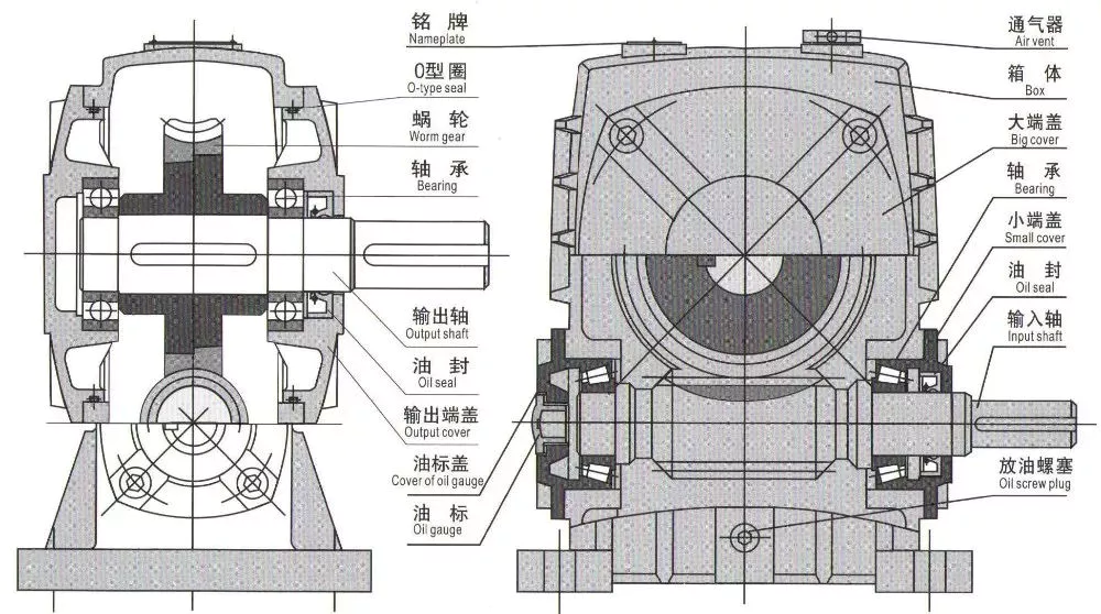
Coaxial helical gearbox
The Coaxial helical gearbox is a highly efficient transmission system that is well suited for light-duty applications. Compared to spur-type gearboxes, the real pitch of a Coaxial helical gearbox is low at all helix angles. This is because the coaxial type has the same number of teeth and center gap as the spur gearbox. Coaxial helical gearboxes also have a smaller footprint and are compact.
Several nations have implemented lockdown regulations for Industrial Gearbox trade, threatening the global economy. Several factors have been implicated in COVID-19, including supply chain, market, and financial markets. Experts are monitoring the situation globally and project remunerative prospects for gearbox manufacturers after the crisis. This report depicts the latest scenario and offers a comprehensive analysis of COVID-19’s impact on the entire industry.
This Coaxial helical gearbox features a compact structure and high precision gear. Its three-stage design combines two-stage gears with a single-stage gear, forging high-quality alloy steel for high precision and durability. The gears are serially-designed for easy interchangeability. They are also available in high-frequency heat-treated steel. A Coaxial helical gearbox is the perfect solution for many applications.
Coaxial helical gearboxes have the added benefit of using cylindrical gears instead of shafts. They operate quietly, and have more surface area to interact with. Their fixed angles make them suitable for heavy-duty applications, like in conveyors, coolers, and grinders. Compared to other gearbox types, Helical gearboxes have higher power-carrying capacity. Listed below are the benefits of a Coaxial Helical Gearbox
Skew bevel helical gearbox
A Skew bevel helical gear box is a common type of industrial gearbox. These gearboxes are rigid and compact and can be used in a variety of applications. They are commonly used in heavy-duty applications such as grinding mills, conveyors, and coolers. They are used in many applications to provide rotary motions between non-parallel shafts. They also have the added benefit of high-efficiency in a variety of industries.
Skew bevel helical gear boxes are suitable for heavy loads and are monolithic in construction. This type of gearbox combines the benefits of bevel and helical gears for right-angle torque, which makes it a popular choice for heavy-duty applications. In addition to being a robust and reliable gearbox, these gearboxes are highly customizable and can meet almost any industrial need.
To maximize the efficiency of bevel gears, FE-based tooth contact analysis is used to develop a sophisticated geometry optimization algorithm. The software also allows users to define optimal flank topography by introducing application-specific weightings for specific load levels. With this data, a manufacturing simulation is conducted to determine the best variant. A robust variant combines the benefits of efficiency, load-carrying capacity, and low excitation behavior.
The helical gear can be angled at 90 degrees. This is similar to a spur gear but produces less noise. It can achieve a nine-to-one speed reduction with one stage. However, a helical gear requires a larger driver gear for higher reductions. This gearbox is suitable for speeds from 1:1 to three times. They are often used in the manufacture of motors and generators.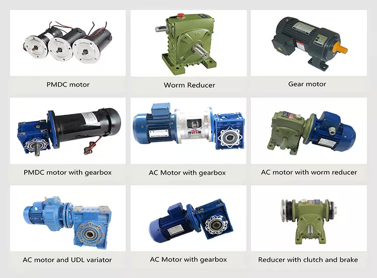
Extruder helical gearbox
An extruder helical gearbox is one of the most common industrial gears. It is compact in size and low-power consuming, making it ideal for heavy-duty applications. Extruder helical gearboxes are suitable for a variety of industrial applications, including cement, plastics, rubber, conveyors, and coolers. In addition to its use in plastics and rubber manufacturing, this gearbox is also useful in other low-power applications such as crushers, coolers, and conveyors.
CZPT SG series Extruder Helical Gearboxes are available in Single Screw and Twin Screw Variations. These gears feature a compact design, high power density, and long service life. Axial bearing housing and thrust bearings are mounted on the input shafts. Extruder helical gearboxes can be installed in various positions, including horizontal, vertical, and inclined.
Helicoidal gears are often produced in a modular manner. This design provides multiple benefits, including engineering and performance advantages, modular production, and the highest level of component integrity. A single helical gearbox can be assembled into a larger gearbox if needed, but modular production ensures consistent performance and economy. This modular design is also cost-effective. It is a versatile and reliable solution for a wide range of applications.
In addition to its efficiencies, Extruder helical gearboxes also have a low noise profile. They have no squeal sounds, and they are silent when running. They can transfer more power than conventional gearboxes. This type of gear has been used in the manufacturing of high-quality plastic products for years. They are often used for applications in automotive transmissions. Aside from being quiet, helical gears have higher contact levels and lower vibration.


editor by czh 2022-11-25